
How to Use a Breadboard: Complete Beginner's Guide for Electronics
Introduction to Breadboards
A breadboard is an essential tool for anyone interested in electronics, hobbyists, and students learning about circuit design. Whether you're building your first LED circuit or prototyping a complex electronic project, understanding how to use a breadboard is fundamental to your success. In this comprehensive guide, we'll walk you through everything you need to know about breadboards, from basic concepts to practical applications.
What is a Breadboard?
A breadboard (also called a solderless breadboard or protoboard) is a rectangular plastic board with multiple small holes arranged in a grid pattern. These holes are connected internally by metal clips that allow you to insert component leads and wires without soldering. The term "breadboard" comes from the original practice of building circuits on actual wooden bread cutting boards!
Breadboards are primarily used for:
- Prototyping circuits without permanent connections
- Testing electronic designs before final assembly
- Educational purposes for learning electronics
- Rapid development of electronic projects
- Reversible experimentation without damaging components
Understanding Breadboard Layout
Most standard breadboards follow a predictable layout pattern:
Terminal Strips
The majority of a breadboard consists of terminal strips. Each row of five holes (or groups of holes) is internally connected. This means that if you insert a wire into one hole in a row, it's electrically connected to any other component lead inserted in another hole in that same row.
Power Rails
Along the edges of the breadboard, you'll find power and ground rails (usually marked in red and blue). These run vertically and provide convenient connection points for power (+) and ground (-) throughout your circuit. These rails are essential for distributing power to all your components.
Ground and Positive Rails
- Red rails (positive): Connect to your power supply (+)
- Blue/Black rails (ground): Connect to your power supply's negative terminal
Types of Breadboards
1. Full-Size Breadboards
The most common type, with 400-900 connection points. These offer ample space for complex circuits and are ideal for projects and learning.
2. Mini/Half-Size Breadboards
Smaller versions with 170 connection points, perfect for portable projects and simple circuits.
3. Experiment Kits
Pre-assembled boards with built-in power supplies and other features for educational use.
4. Soldered Breadboards
For permanent projects, some makers upgrade to soldered breadboards to ensure reliable long-term connections.
Step-by-Step Guide: How to Use a Breadboard
Step 1: Gather Your Materials
Before starting, ensure you have:
- A breadboard
- Electronic components (LEDs, resistors, capacitors, etc.)
- Jumper wires (in various lengths)
- A power source (battery or power supply)
- Optional: a circuit diagram or schematic
Step 2: Plan Your Circuit
Always start with a circuit diagram. Understanding the flow of current and connections is crucial. Popular resources for circuit diagrams include:
- Arduino.cc - Arduino Project Hub
- SparkFun - Electronics Tutorials
- Adafruit - Learning Resources
Step 3: Organize Your Components
Arrange your components logically. Keep similar components together and plan your layout to minimize crossing wires, which can make circuits confusing and prone to errors.
Step 4: Insert Components
Carefully insert component leads into breadboard holes. Push gently until the lead is fully inserted. Ensure leads sit properly in the holes for good electrical contact.
Step 5: Connect Power Rails
Connect your positive power supply to the red rail and negative (ground) to the blue rail using jumper wires. This provides power to all your components easily.
Step 6: Create Your Circuit
Using jumper wires and following your circuit diagram, connect components as planned. Remember: holes in the same row are connected internally.
Step 7: Test Your Circuit
Before powering up, double-check all connections against your circuit diagram. Verify polarity on polarized components like LEDs and capacitors. Once verified, connect your power source and test functionality.
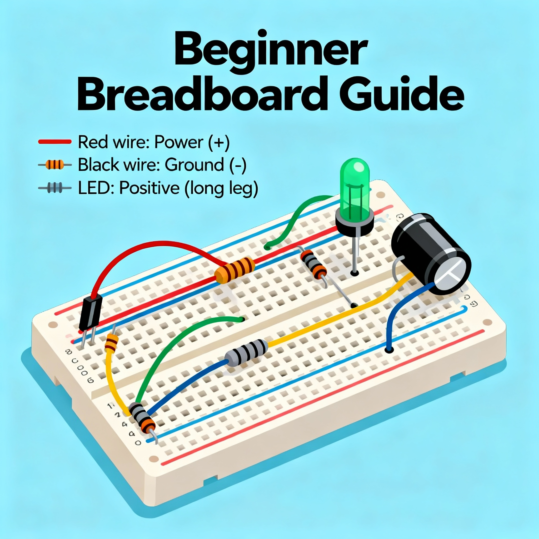
Practical Example: Simple LED Circuit
Let's build a basic LED circuit:
- Insert an LED into the breadboard (longer leg = positive)
- Connect the LED's positive leg to a resistor (typically 220-330 ohms)
- Connect the resistor to the positive power rail
- Connect the LED's negative leg directly to the ground rail
- Connect your power supply
- The LED should light up!
Note: Always use a resistor with LEDs to limit current and prevent damage.
Important Tips and Best Practices
1. Always Use Resistors with LEDs
LEDs require current limiting through resistors (typically 220-330 ohms for 5V circuits). Without resistors, LEDs will burn out immediately.
2. Check Polarity
Capacitors, diodes, and LEDs are polarized components. Incorrect polarity can damage components or cause circuit malfunction.
3. Use Jumper Wires Correctly
Avoid bending wires excessively. Use appropriately sized jumper wires to keep circuits neat and organized.
4. Keep It Clean
Remove unused components promptly. Cluttered breadboards increase the chance of accidental short circuits.
5. Power Supply Safety
Always start with lower voltages (5V or 9V) when learning. Verify your power supply voltage matches your circuit requirements.
6. Test Before Permanent Installation
Breadboards are perfect for testing. Only solder circuits once you've verified everything works correctly.
7. Label Your Wires
Use colored jumper wires or labels to identify power, ground, and signal lines. This makes troubleshooting easier.
8. Document Your Circuits
Take photos or keep diagrams of working circuits for future reference.
Common Mistakes to Avoid
- Incorrect pole placement: Double-check power and ground connections
- Using too much force: Gently insert components; forcing them can damage the breadboard
- Poor wire connections: Ensure all wires are fully inserted
- Mixing up component values: Always verify resistor and capacitor ratings
- Ignoring component polarity: Respect + and - markings
- Loose connections: Reinforce weak connections by adjusting wire position
Breadboard Alternatives
Once you master breadboards, you might explore:
- Perfboards: For more permanent designs
- PCB (Printed Circuit Boards): For professional-quality circuits
- Wire wrapping: An alternative to soldering
- SMD (Surface Mount Device): Advanced component mounting
Conclusion
Breadboards are invaluable tools for anyone learning electronics or prototyping circuits. They offer a quick, reversible way to experiment with electronic components without the permanence of soldering. By following this guide, you now understand how breadboards work, their internal connections, and how to build your first circuits safely and effectively.
Start with simple circuits, practice proper techniques, and gradually tackle more complex projects. The skills you develop using a breadboard will serve you well throughout your electronics journey.
References and Further Learning
- Arduino Project Hub - https://create.arduino.cc/projecthub
Official Arduino tutorials and project guides for beginners - SparkFun Electronics - https://learn.sparkfun.com/
Comprehensive electronics tutorials and breadboard guides - Adafruit Learning - https://learn.adafruit.com/
Detailed guides on components and breadboard usage - All About Circuits - https://www.allaboutcircuits.com/
Free, comprehensive electronics textbooks and tutorials - Electronics Tutorials by TE - https://www.electronics-tutorials.ws/
Easy-to-understand electronics fundamentals - Wikipedia - Breadboard - https://en.wikipedia.org/wiki/Breadboard
Historical and technical information about breadboards
Happy building! Remember, every electronics expert started exactly where you are now. Keep experimenting, learning, and creating amazing projects with your breadboard.